


Welcome to The Veteran SDR design history.
This radio is the culmination of many years of experimentation and research with SDR radios of all types. Many of the design ideas are not of my own. Credit has to be given to many folks who spear headed this technology. Tasa YU1LM with his work on the Avala-01 and Genesis Radio, Gerald Yongblood and his SDR1000, Softrock radios and many folks from their web forum, Steve Haynal for his work with the Hermes Lite project, Open HPSDR for their Hermes project, Lima SDR for their pre-selector circuit and many other OMs will to share their experiences with SDR all over the Web. A special thanks goes to Fred Krom, PE0FKO, for his work with the AVR Firmware and CFGSR to control the Si570 oscillator.
This project originally started out as a proof of concept for reducing the close in spur issue with Tayloe QSD/QSE radios. These radios are typically connected to a sound card then attached to a computer. Much has been discussed about the close in spurs associated with the QSE during transmit. The LO leakage can be quite high, some times only -35dbc. The other issue with the LO leakage is this amplitude is not linear across the bands. Lower bands are generally better with the upper bands very high. This can be adjusted with proper circuit tuning when dealing with mono or dual band radios. But if you are trying to cover the entire HF spectrum you will find LO leakage adjustment very difficult, if not impossible, across all bands. Some radios use trimmers to control the voltage prior to the QSE but again this leakage is not linear. The Avala-01 and Genesis radios use this type of set up. The Softrock Ensemble RXTX, if you were to make multi-band HF, would not have any adjustments. Some ideas I saw used the trimmer type setup but with banks of trimmers that would switch when a particular band group is selected. The results were mixed. Some had success and other not. In my opinion this is way too complex. So the search was on for a solution that was not too difficult.
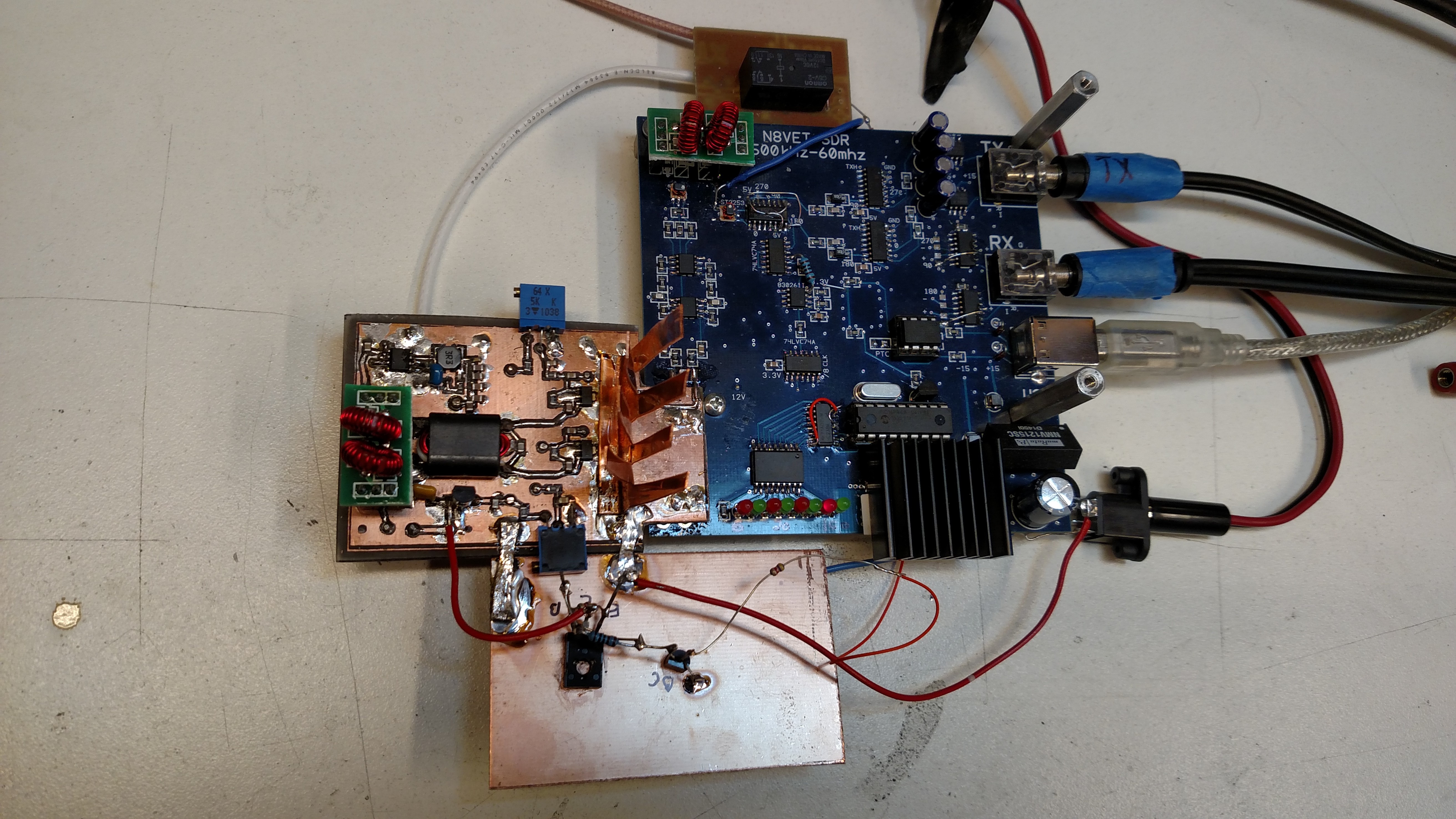
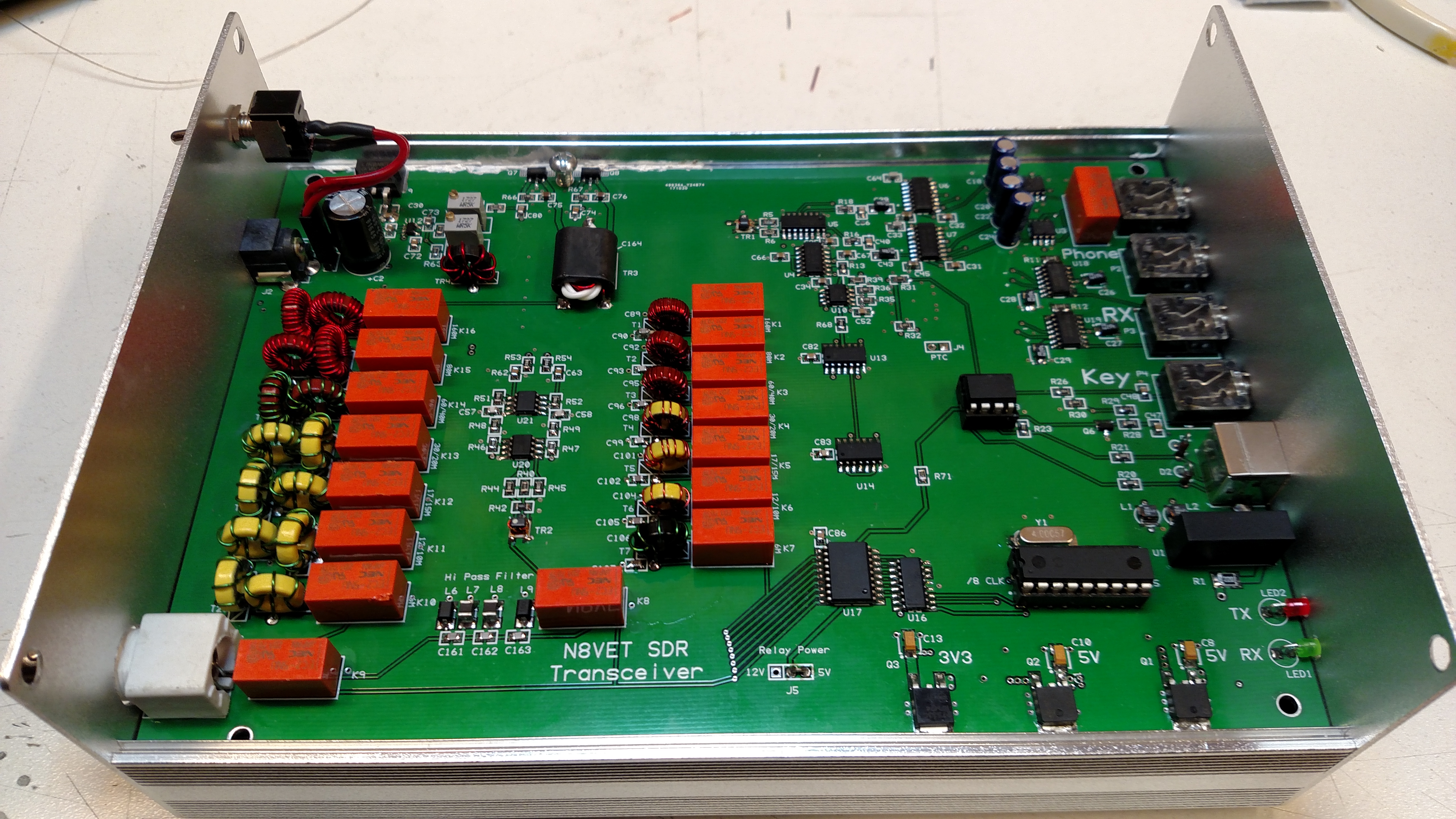
I found some OMs doing some experiments and having some success in this area. The main idea was to have the TX circuit, QSE and divider in close proximity to each other. Trace runs as direct as possible. This led to my first concept board. To simplify the circuit I used the SDR1000 INA163 and DRV135 as the audio OP Amps. Very few parts with this circuit. I decided to use a single Mixer(QSD/QSE) CBT3253. Generally there seems to be two trains of thought here. Have two completely separate CBT3253(TX and RX) or combine them into one CBT3253. I decided on the later, again for simplicity sake. To switch the audio between RX and TX I'm using a pair of 74HC4053 which have pretty good channel isolation in the -90db range at 10khz. Much better then any relays. I also designed the PCB with 4 layers. I felt this was very critical for return paths to ground. Plus the power circuit would have some isolation too. I added a low power Amplifier borrowed from the Hermes radio to boost the Mixer output. A pair of OPA2674 in push/pull configuration for low IMD. This board is pictured below. As you can see it sure is a home brew project!
The results were very good in my opinion. LO leakage was at least -52dbc or better on all bands. IMD tests were very good too. Because I almost have a complete radio now I decided to add a 5W PA borrowed from the Hermes Lite project. PA features a pair of 3W LDMOS SMD devices in push/pull. Sure enough I had 5W across all HF bands. Spurs and IMD are still good.
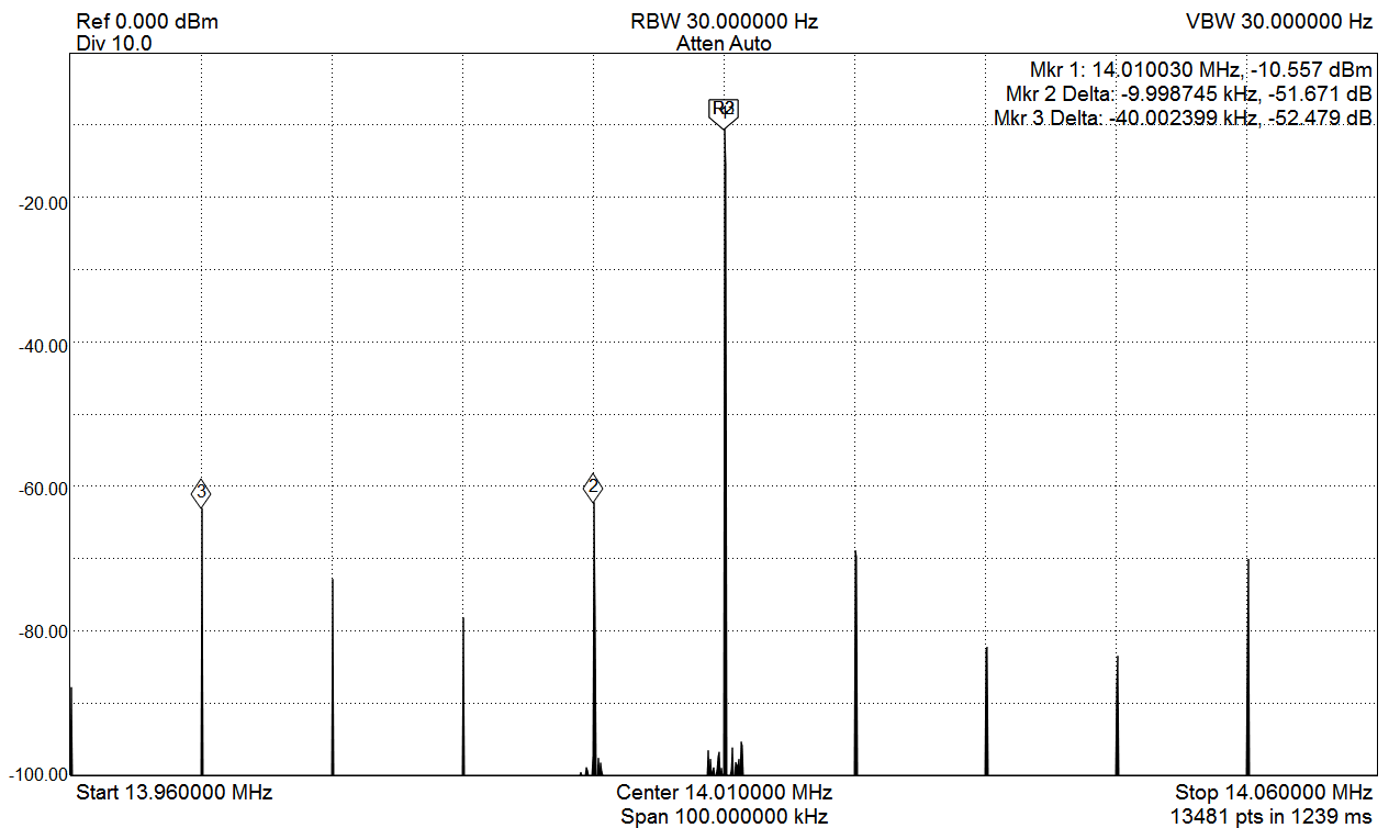
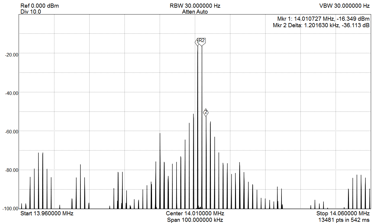
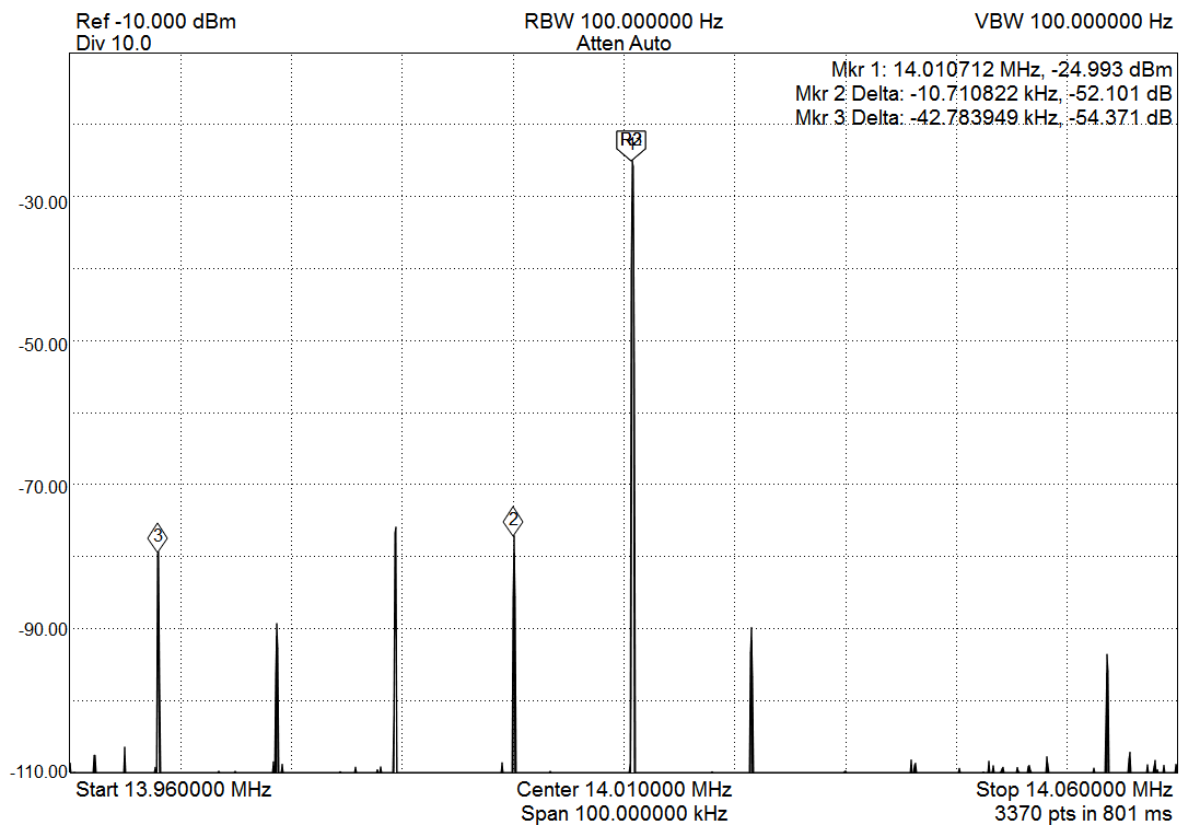
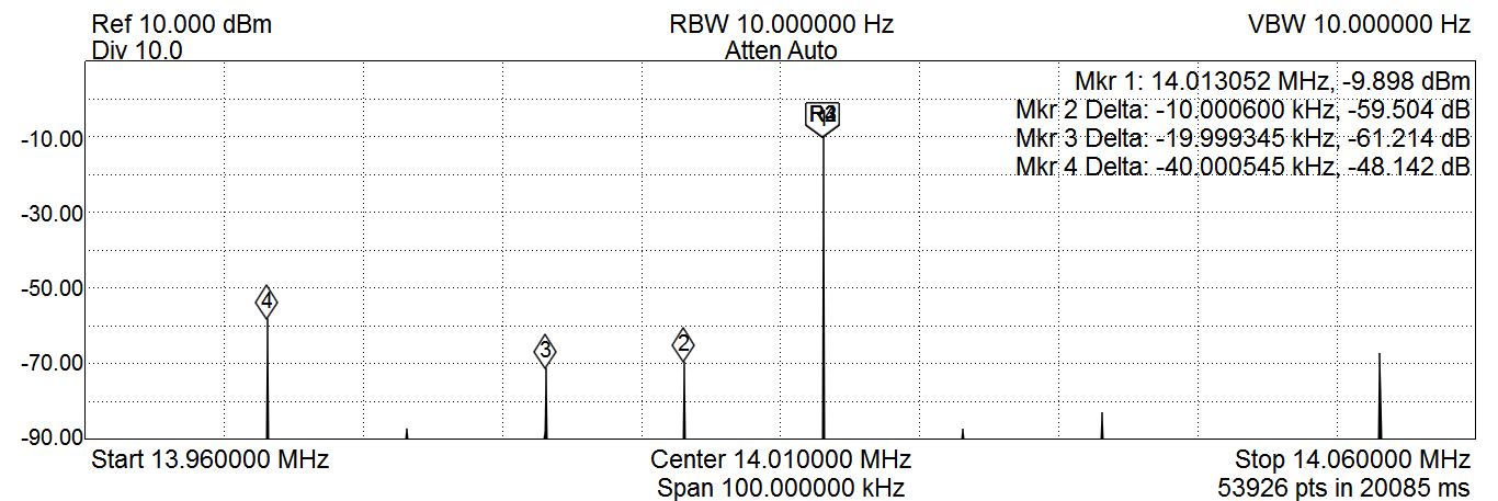
The next item of concern deals with another spur that can be quite high if you push the audio drive too hard. I call it the 4xLO Offset spur. See picture below. Carrier is set to 7.06mhz with the LO at marker 2. This is a 4.3khz IF shift(LO offset from carrier). Marker 3 shows the TX image which is software adjustable. Marker 4 shows the 4xLO Offset Spur(4x 4.3khz=17.2khz) without any filtering after the mixer. Actually the offset is a little more than 4.3khz resulting in 17.5khz in picture. It has been determined by folks on the Softrock forum that this spur is caused by reflections from the 3rd harmonic.
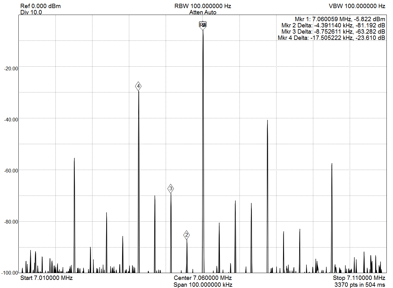
This spur can not be adjusted with software or hardware, well almost. This spur can be reduced with a LPF/BPF right after the Mixer and prior to the PA circuit. Most radios use a BPF which is also used during RX. The filter does not need to be too aggressive with steep skirts. A simple 3 pole LPF will suffice. Because this filter is used with RX too then a BPF would be quite suitable as long as the pass band has low losses. We don't want to much reflected back to the Mixer! At any rate, this filter should bring the 4xLO Offset spur below the -43dbc threshold. In addition the level of drive has a direct affect on this spur. Trying to get every mW out of the amp will cause you to QRM adjacent channels. Think about it. A Ham 17khz away will definitely hear your signal! Maybe not at the 5W QRP level but if you run that signal through a 50 or 100W amp then it becomes an issue. Never mind trying 100's of Watts.
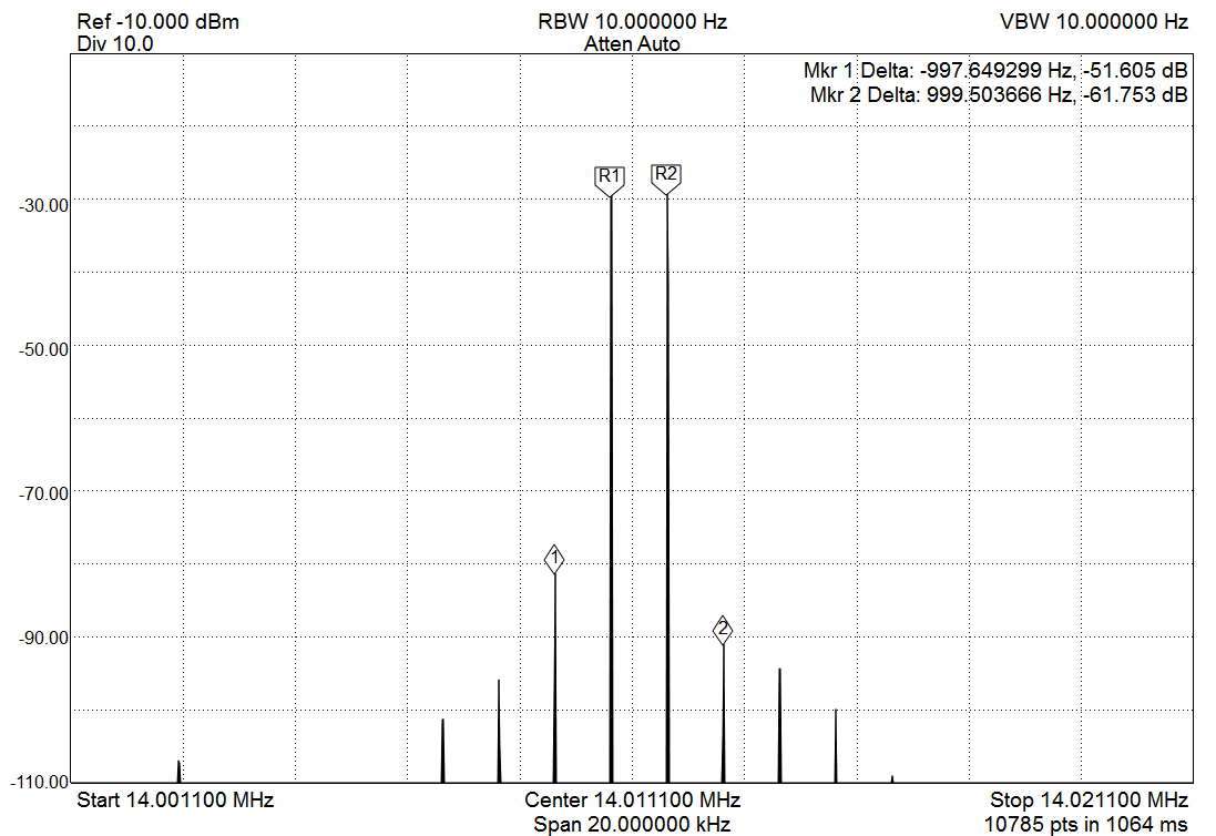
What is comes down to a balancing act between drive level and your amplification chain. The drive from the Mixer needs to be high enough to give a good separation between the LO signal and the carrier. -60dbc is a good starting point. Further down the PA chain this split will be amplified nearly equally. This output level is the Max drive from the Mixer. What ever you want as final output needs to made up with pre-amp and final amp stages.
My board uses push/pull for pre-amp and final stages for better linearity. Plus, with this type Amp the second harmonic is greatly suppressed so the LPF does not need to have steep skirts, resulting in easier and repeatable construction. I used the radio for several weeks as pictured and completed many QSOs. It became a hassle switching the filter modules so I thought it would be great to have a PCB with all the filters. This led to my revision 1 PCB below. With this design I used a simple 3 pole LPF after the mixer. Also below are few Spectrum Analyzer sweeps. LO Leakage is getting better!
The 4x LO Offset, in my opinion, could be reduced further with redesigned Mixer filter specifically tuned to reduce the 3rd harmonic and very low loss pass band. This resulted in Revision 3 shown below. Results are still pretty good. I added provisions to attenuate the TX signal prior to and after the Pre-Amp help in tuning the PA chain. I also decided to go with one Driver IC, an OPA2677. With this setup I wasn't getting quite the drive I needed for the PA so I had to bring the drive up higher than I wanted to get 5W output. Hence the 4xLO Offset spur is higher than it needs to be. Still well within specs.
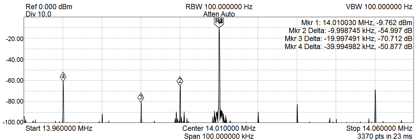
The need to further improve this radio led to Revision 5. With this revision I went back the dual OPA2674 Pre-Amp. I decided to drop the HPF and go with BPFs after the Mixer based on the Proficio SDR. Now the results are where I like it. Plenty of room with the spurs to connect this radio with high output Amplifiers. Once all of this is finalized I plan to offer this PCB for sale so others can benefit from this design. Maybe even a kit will be offered. Parts price from Digikey in the $140 range. Not too bad for an all band HF 5W transceiver with clean output and pretty good IMD performance.
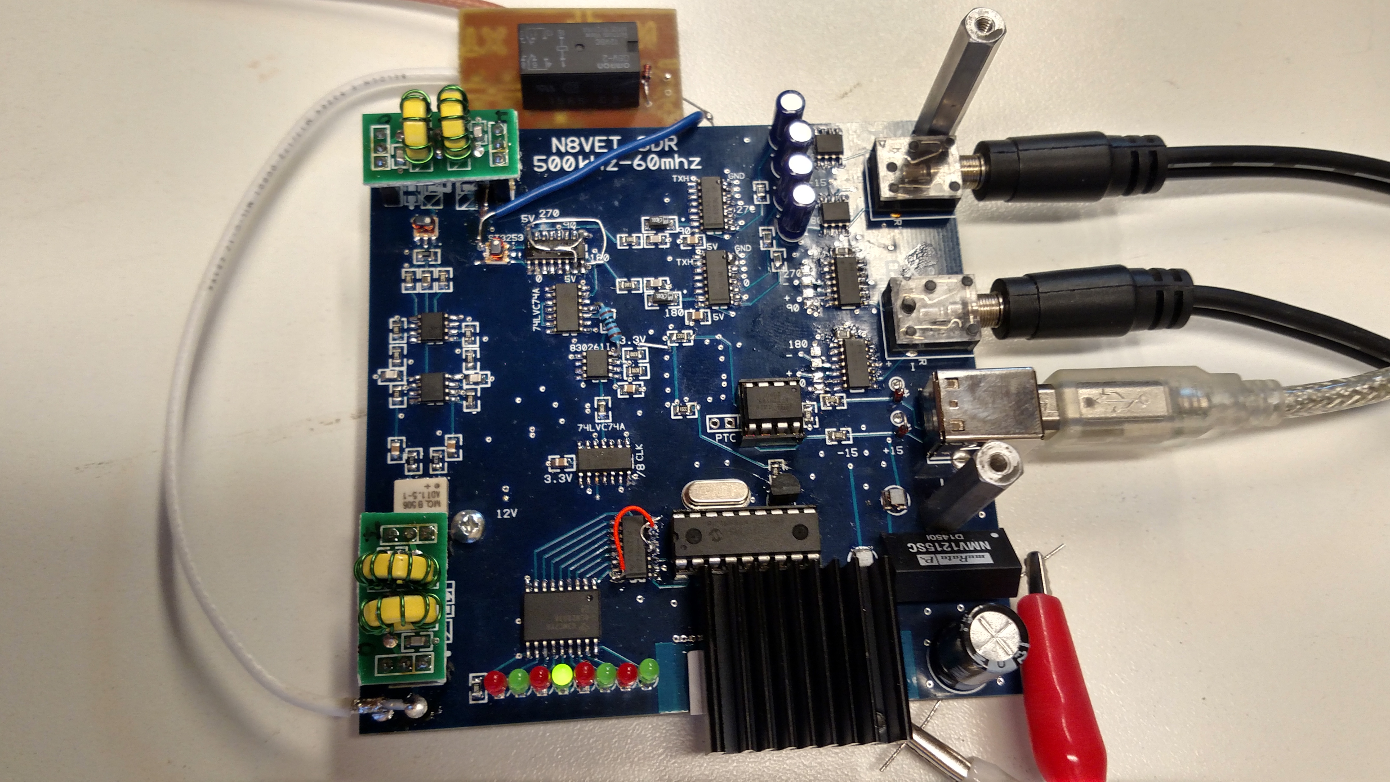
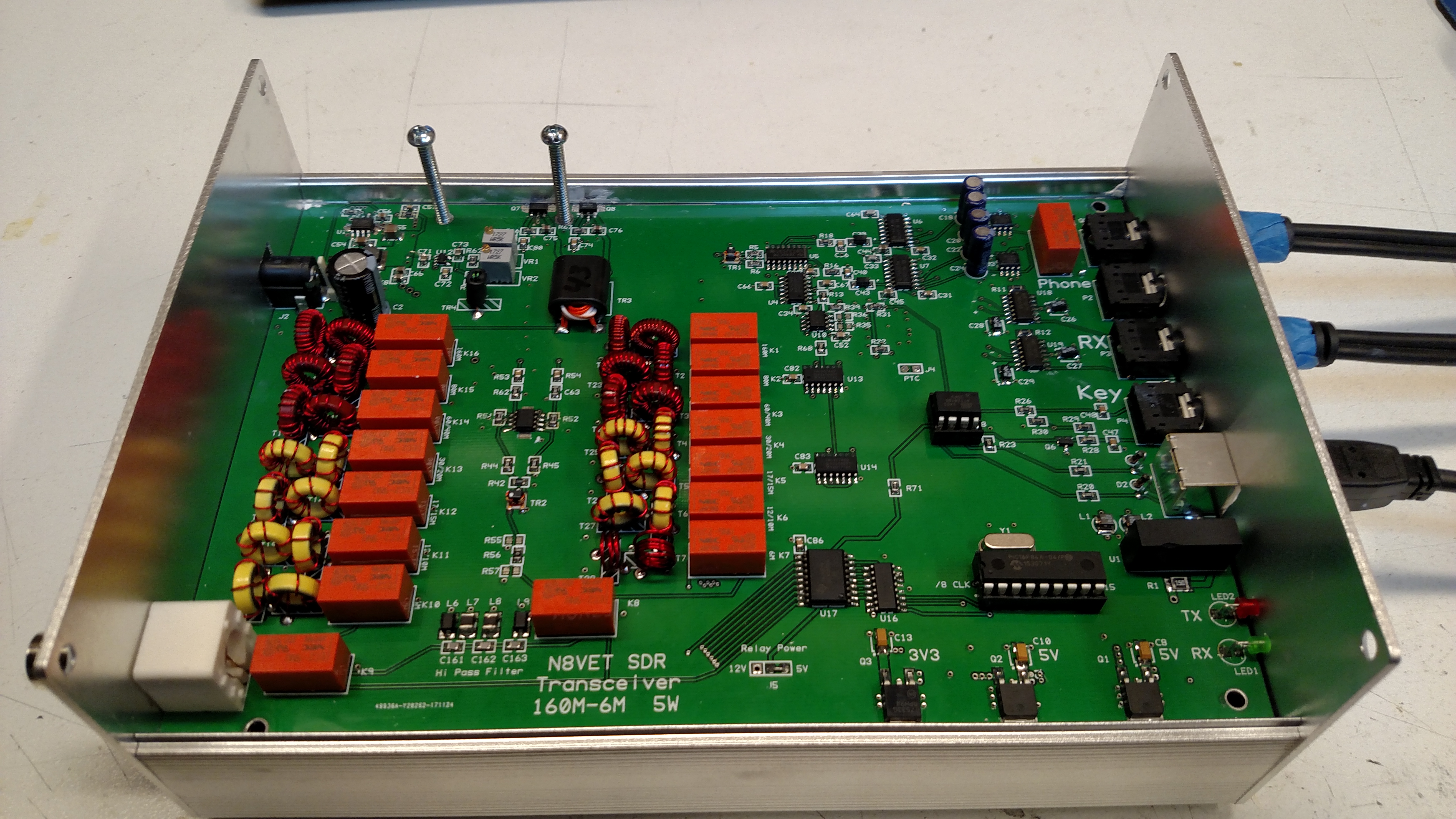
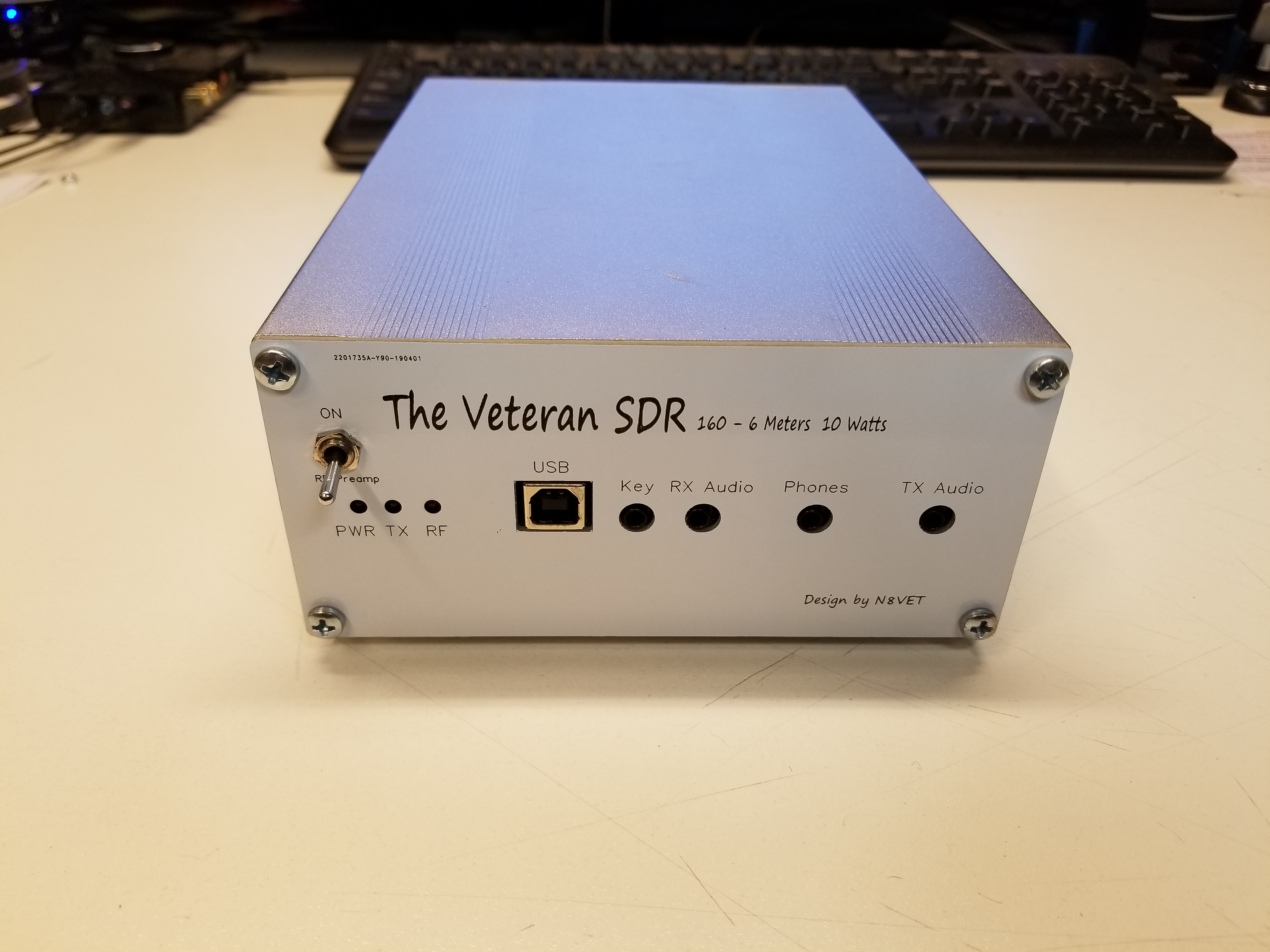
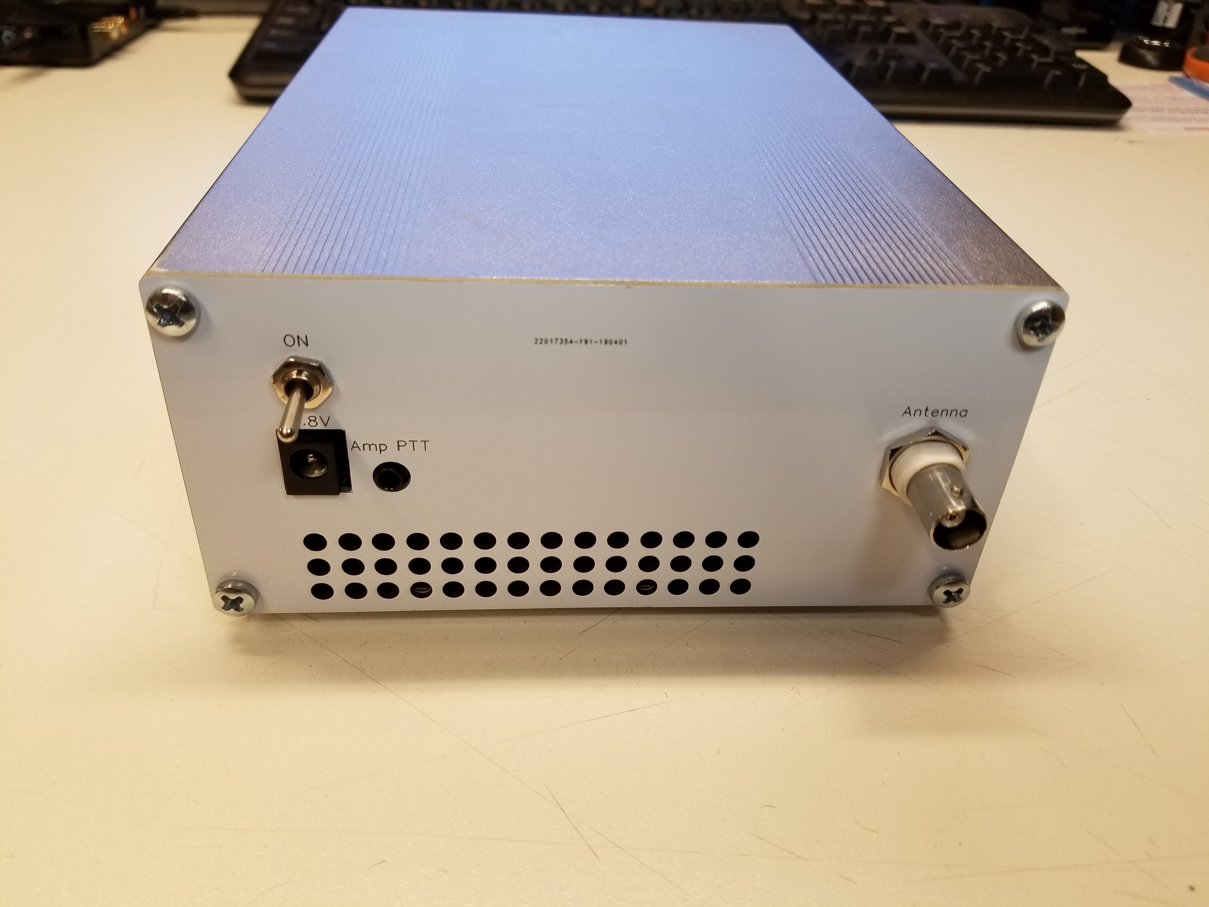
It has been a while since updating my project. I went though a couple more design changes and sent a radio to a friend for testing. One issue which has been nagging at me and verified by a fellew Ham is the vulnerablility of the finals to be over driven thus leading to a failure to one or both. Sometimes when they fail it will cause a short to ground and some pretty impressive smoke. I added a resetable fuse to the power feed to help reduce a board damage but it seemed I needed to find a better solution for the final PA. I also wanted more power in the 10W range. I decided on a pair of RD15HVF1's in push/pull configuration. The results are quite good with over 10W on most bands and 5W on 6M. Below are few pictures. I also made some end plates made of PCB to finish up the design. The heat sink is now mounted under the PCB and securely attached to enclosure. A small fan is installed blowing out the bottom to keeep the enclosure tempuratures stable. A samll tempurature controlled fan PCB is also added.
Some new features added to this version include an RF preamp which is automatically turned off during TX. PTT output to key and external Amplifier(pulled low). The radio now has a name. The Veteran SDR
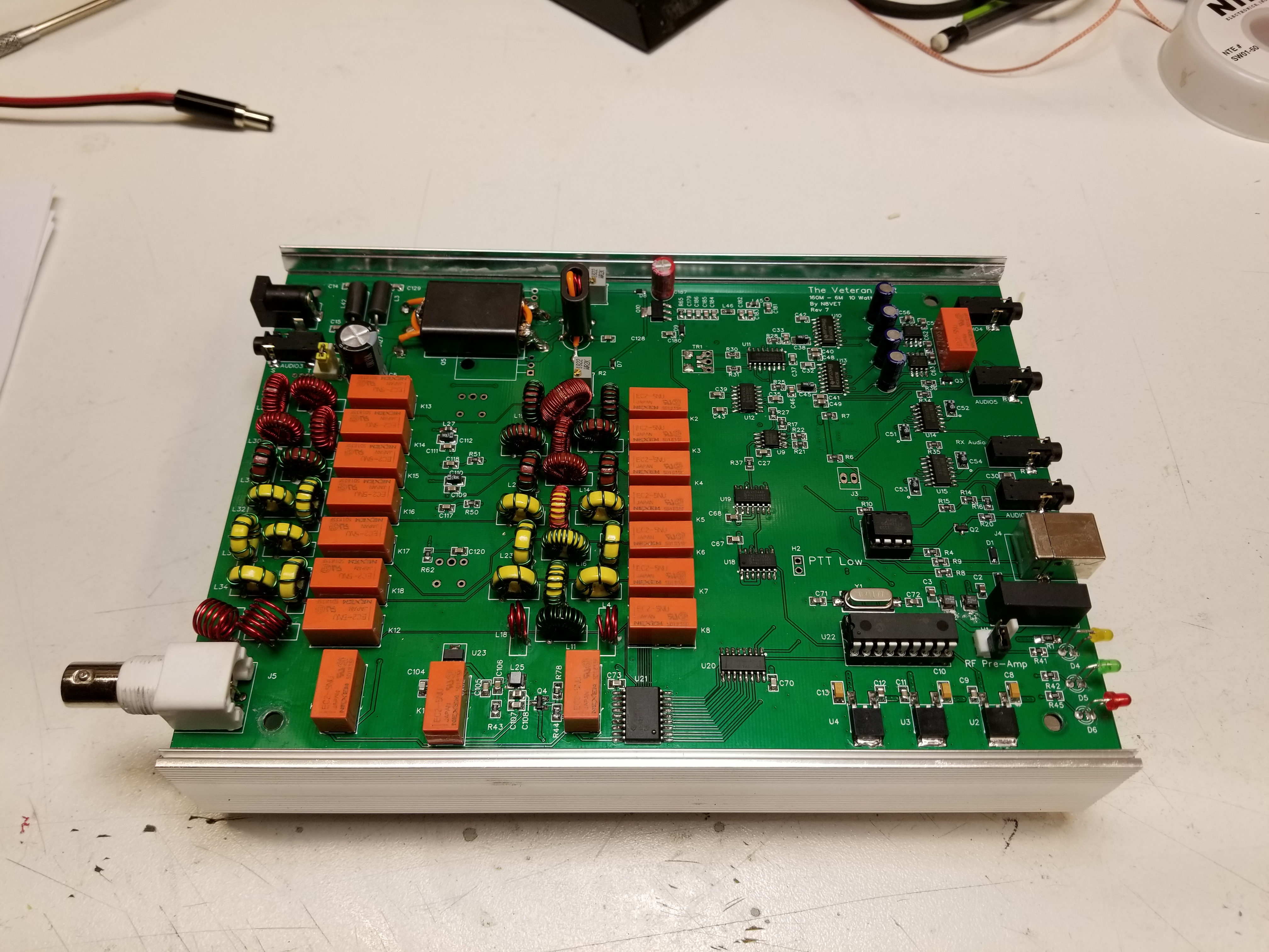
The build went quite well without any major errors. Just one minor issue I ran into. Not bad considering the work involved releasing this version. Up to this point I was basically using 2 programs to design the PCB, KiCad for schematics and Copper Connection for PCB routing. KiCad was very frustrating to get the PCB tool to work so I just stayed with the two programs which made it difficult to detect Netlist errors. Lately for smaller projects I have been using EasyEDA for PCB design and manuafacture. I decided to move this whole project to EasyEDA. The schematics imported from KiCad just fine and then the hard work of redrawing the PCB commenced. At least now any changes can be easily made :)